
BARD PM Mutes Assembly Manual
Introduction
Mutes is an expander module for WMD Performance Mixer. The module was created due to suspension of the original expander production, yet it is not the direct clone - It does incorporate different circuitry to enable soft mute functionality. Use is pretty straightforward - just press the button to mute given channel. Insert control voltage into AUX inputs to have CV control over AUX sends 1-2.
Features
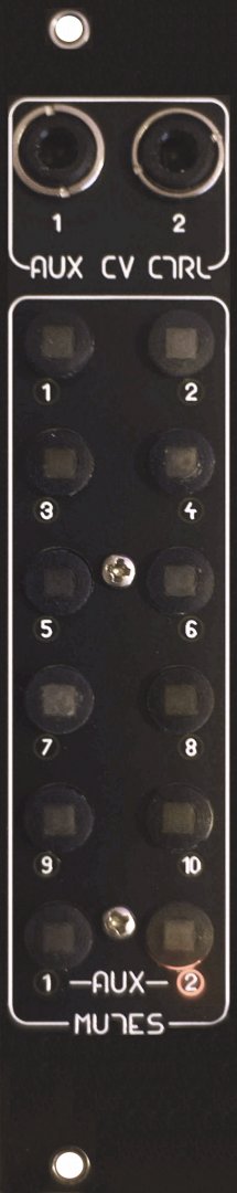
◯ 10 soft mutes for channel inputs ◯ 2 soft mutes for Auxillary channel inputs ◯ 2 Auxilliary Control CV Inputs ◯ Toggle button action ◯ Illuminated on/off state indicators on the panel
Bill of materials
| ID | Check | Name | Description | Qty |
| 1 | pmmutes_B001/PCBA | PCB Assembly | 1 | |
| 2 | SPPH420100 | Push switch | 12 | |
| 3 | FC681375VH | Audio jack, 3.5mm | 2 | |
| 4 | OSO5JA71F4B | LED, orange, square 2x5mm, ~100mcd | 12 | |
| 5 | DS1013-10SSIB1-B-0 | Pin header 2x5 shrouded | 1 | |
| 6 | 77313-818-16LF | Pin header 2x8 unshrouded | 1 | |
| 7 | - | Plastic spacer, M2x13 | 2 | |
| 8 | 1154117 | M2x6 metal screw | 2 | |
| 9 | - | Push button, 7mm dia., compatible with SPPH420100 |
12 | |
| 10 | pmmutes_B001/FP | Front panel | 1 | |
| 11 | - | IDC Cable, power, 2x5 | 1 | |
| 12 | - | IDC Cable, signal, 2x8 | 1 | |
| 13 | M3X8/D7985-A2 | Mount screw M3x8 (for module mounting) | 2 |
Specs
◯ Power consumption: +12V: 0mA -12V: 24mA (max) +5V: 0mA ◯ 5HP wide ◯ 24mm deep
Assembly Instructions
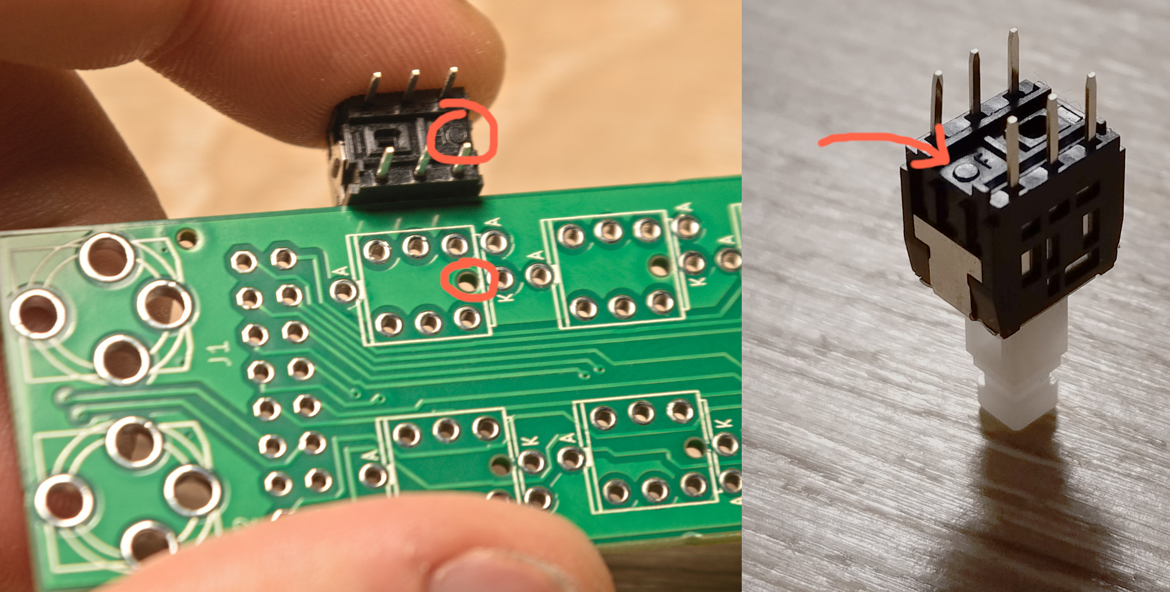
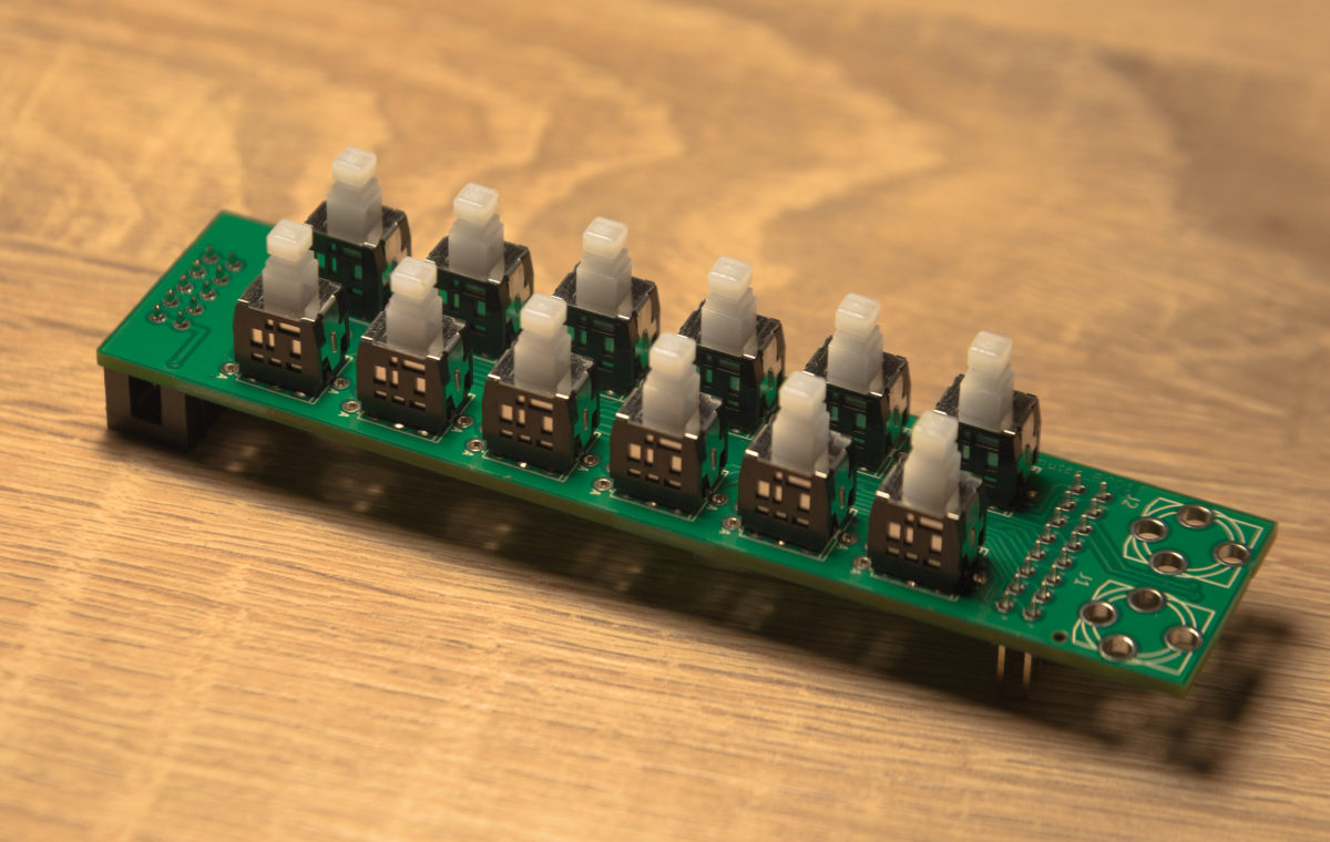
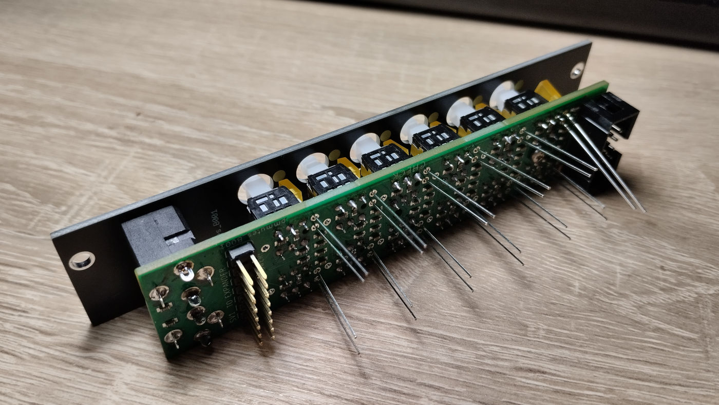
Begin with the push switches. Locate the polarization pin and orient the switch in order to match the one non-plated through-hole inside the silkscreen outline.
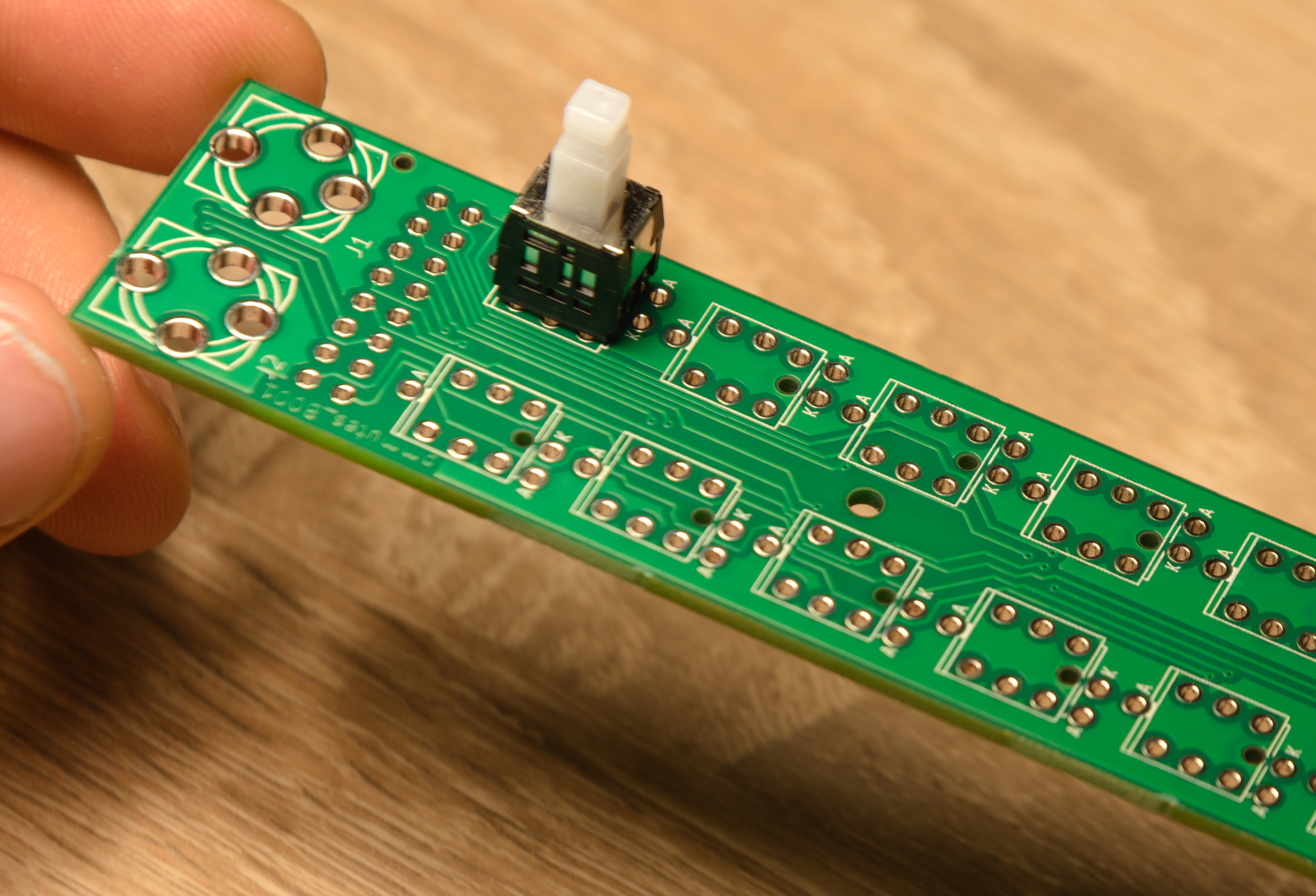
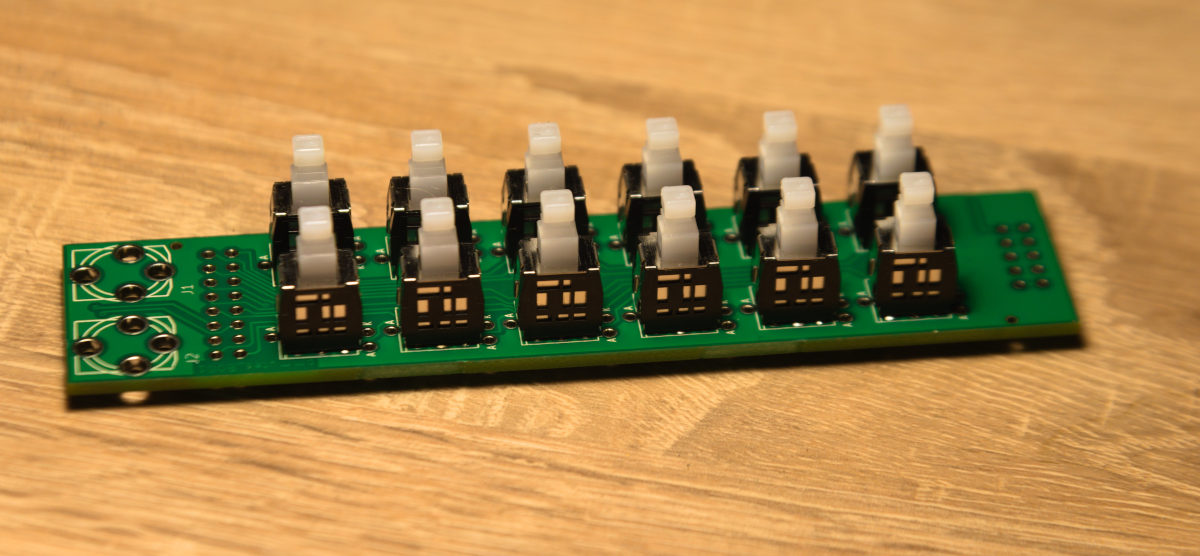
Solder first one of the pins facing the outer egde of the PCB, inspect if it sits perpendicularly to the PCB, then solder the rest of the pins. There shouldn't be any gap between the switch and the PCB. Repeat for the rest of the switches.
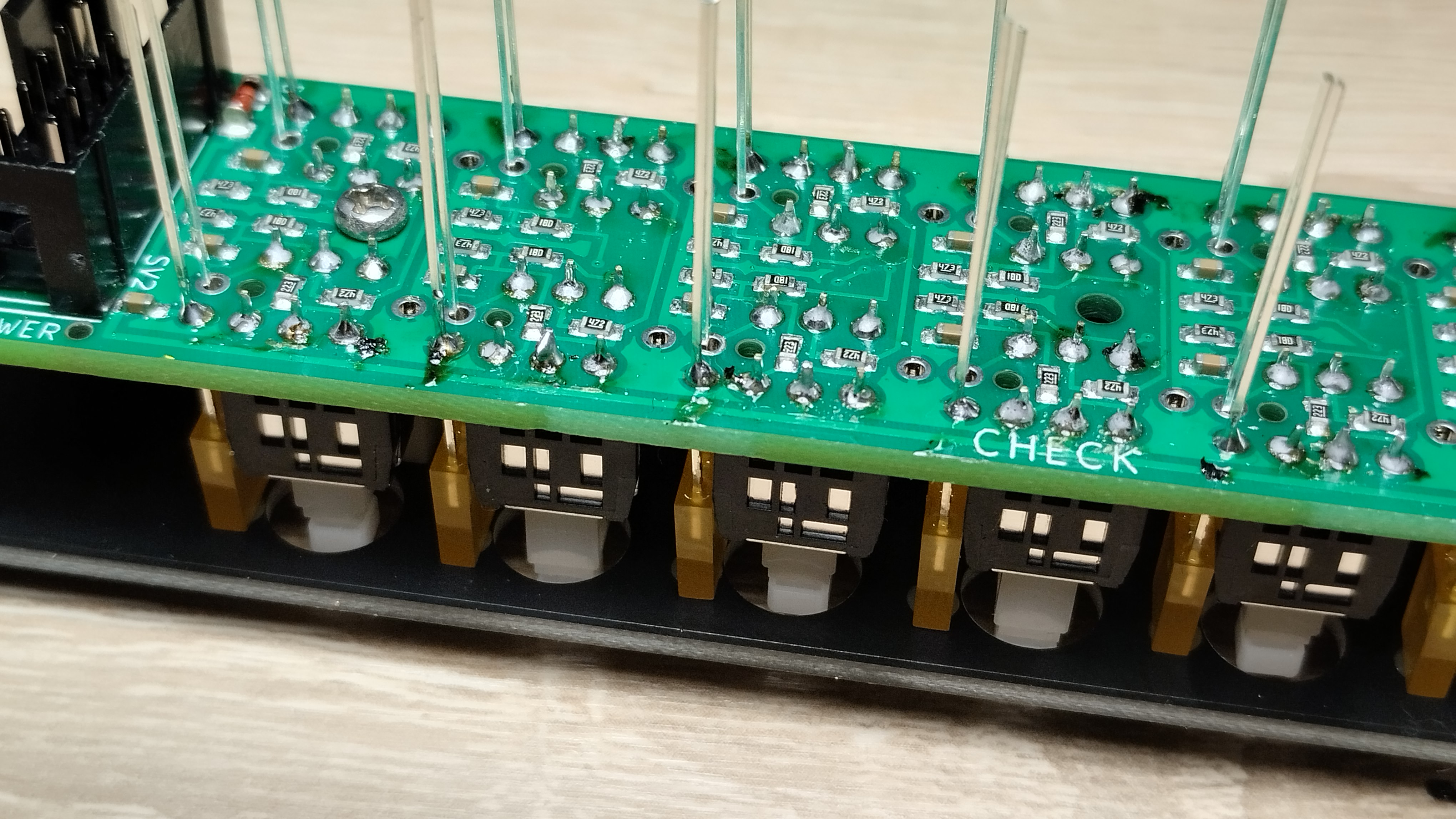
Solder two IDC connectors on the other side of the PCB. Pay attention to the polarizing pin on the 10-pin connector! Silkscreen has the pin marked, as well as the triangle corresponding to the one on the connector.
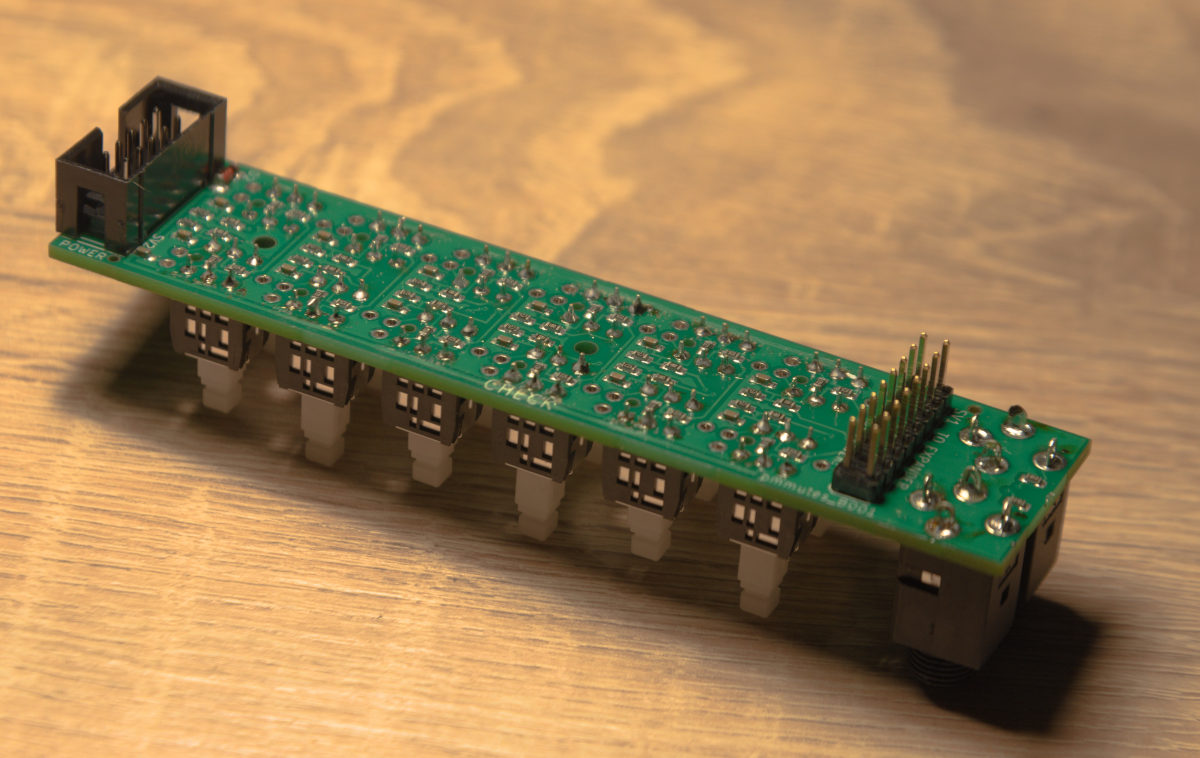
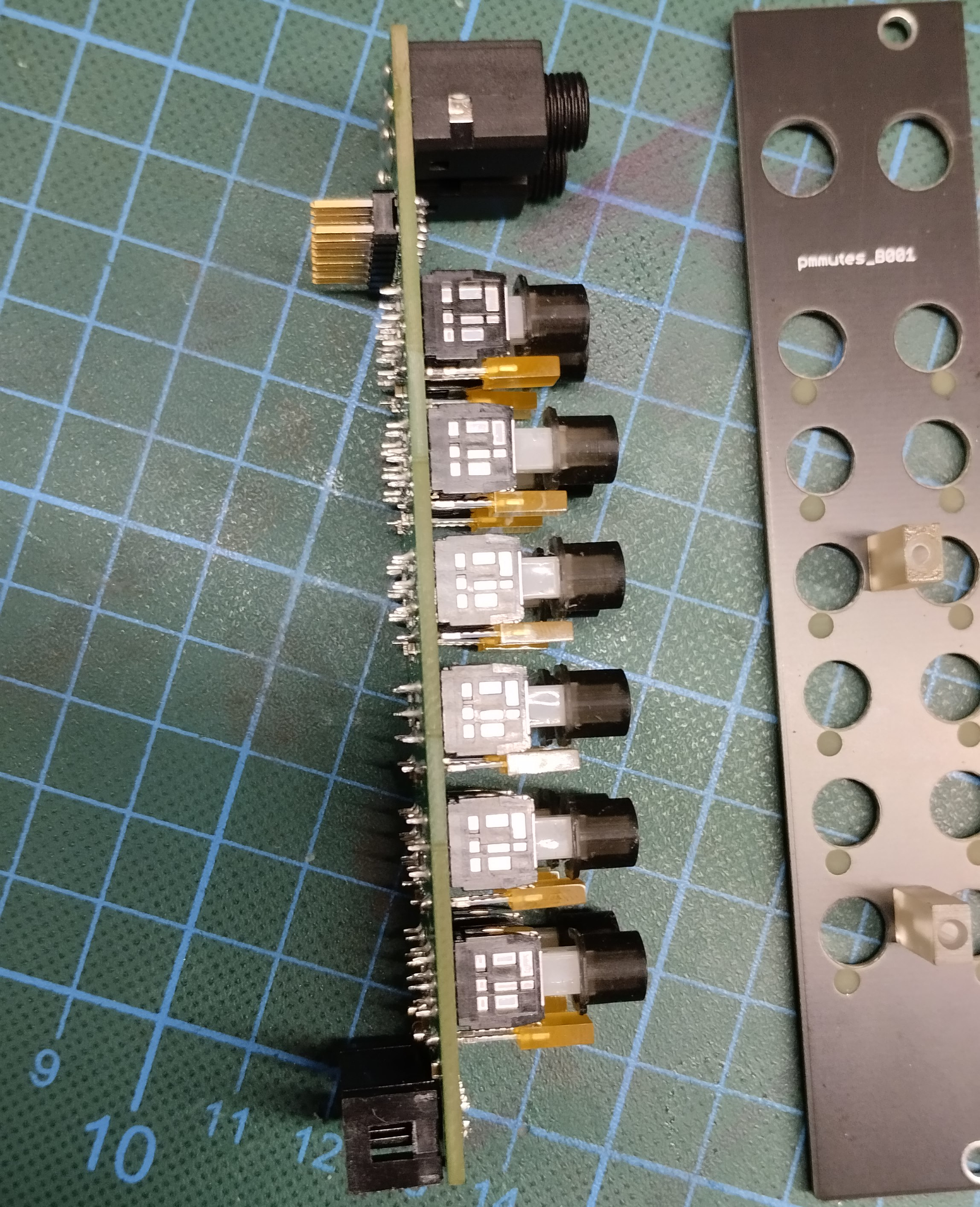
Flip the board again and solder two audio jacks. Take care to align them, you can use the panel as an alignment tool. Also, you don't have to make contact all around the through-hole - solder joint only on the outer edge is okay. Too much solder can slip down the jack pins.
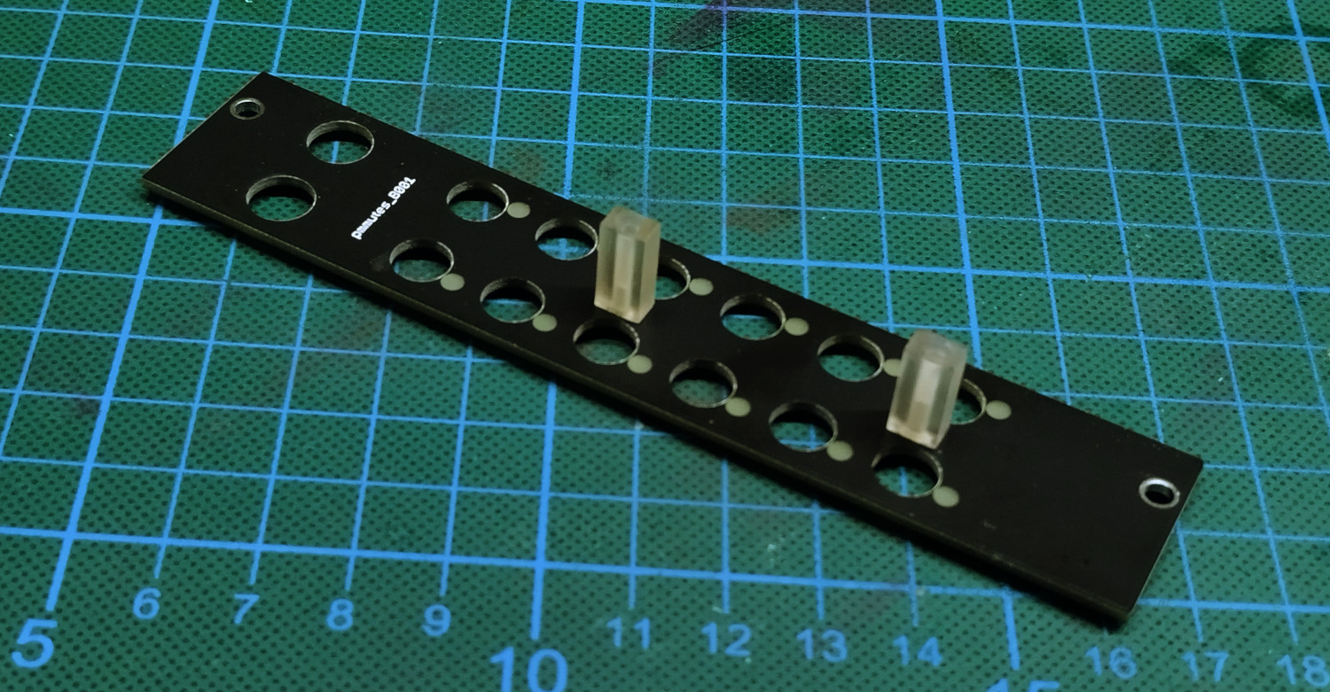
Take the front panel and screw two transparent spacers onto back of it with M2 screws (the smaller ones). Position them as in the photo, with shorter egdes facing switch holes. Use moderate force to tighten, retaining the orientation.
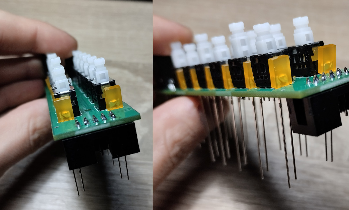
Place all 12 diodes on the PCB. Mind the polarity, longer pin of the diode will go to the A (Anode) through-hole. The other side is mirrored, please pay attention to that as well! Do not solder them yet.
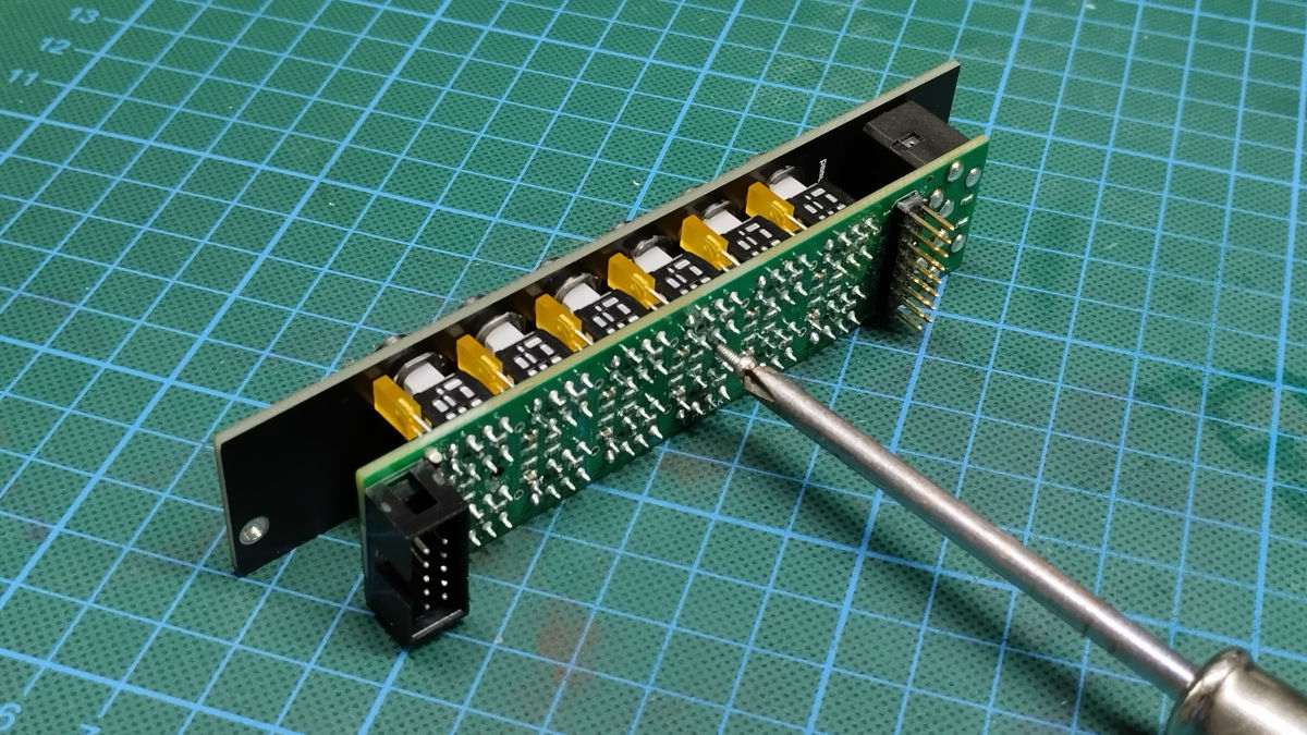
Now, screw in the PCB to panel' spacers using two M2 screws. Also, attach audio jacks with the nuts on the front side. This enables easier diode positioning.
Holding one diode leg, position the diode to be perpendicular to panel (it should touch the front panel as well). Solder one of the legs and repeat for the rest of the LEDs. Verify the positioning and solder the remaining LED legs.
Unscrew the two M2 screws holding the panel from the side of the PCB assembly and attach the push buttons. They're tight fit but can be pressed almost to the end. The LEDs should not collide with the switches across the switches' action, but if that happens, now it's a good time to bend back troublesome LED a little bit.
Reattach the front panel.
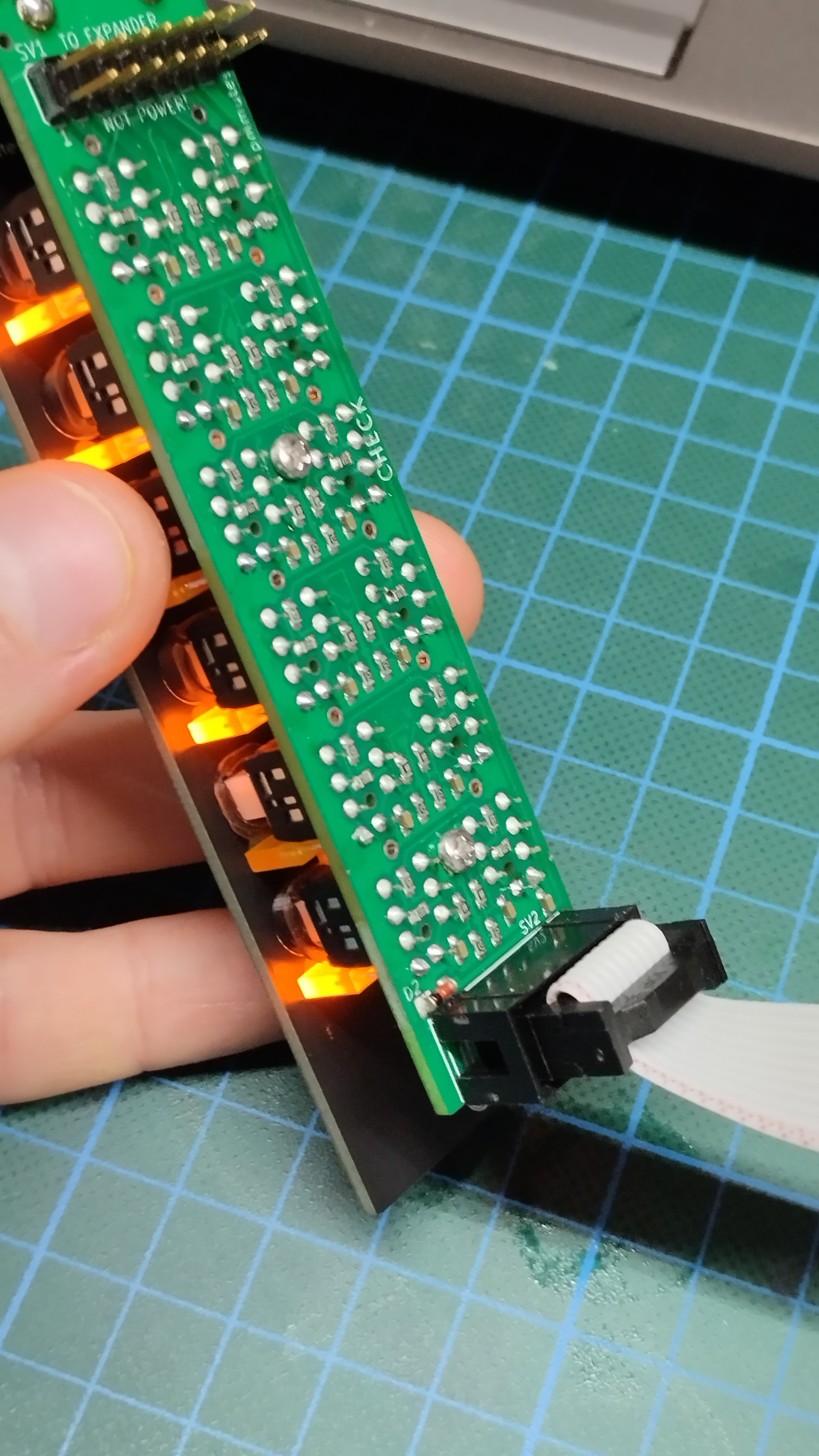
Plug the power in using IDC 10-pin power cable and test if the diodes light up along the button presses.
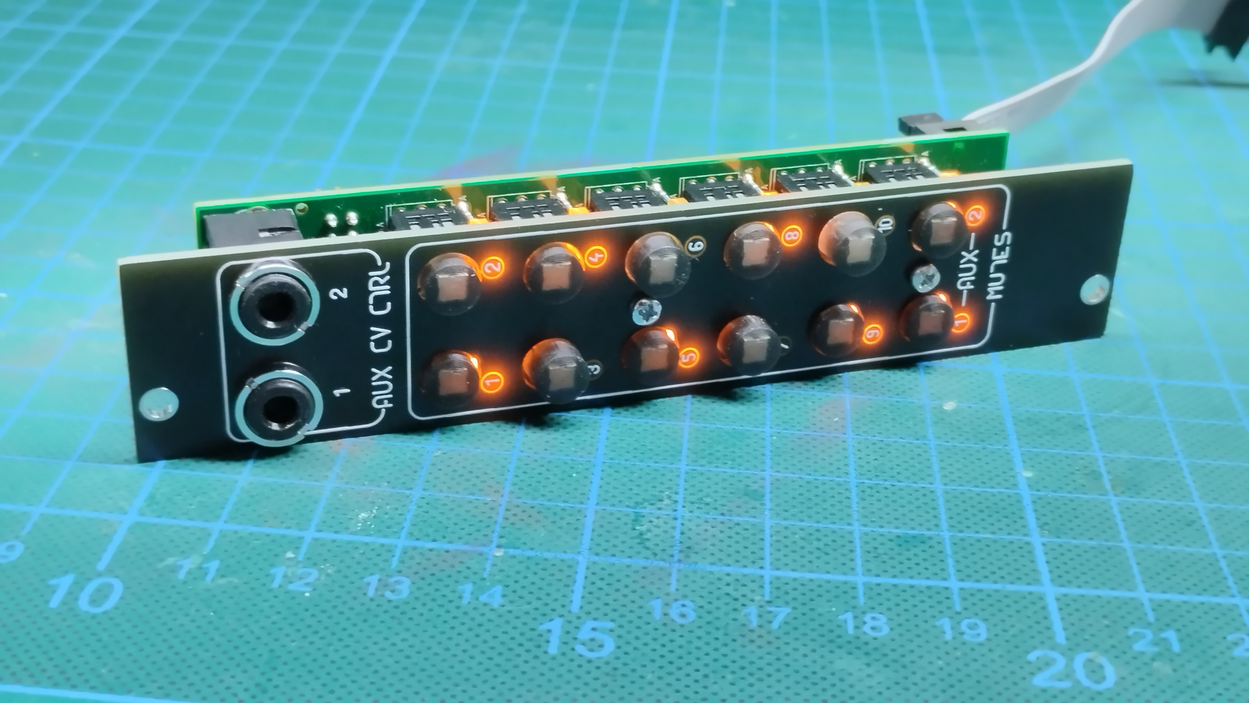
Lastly, fanciness check.
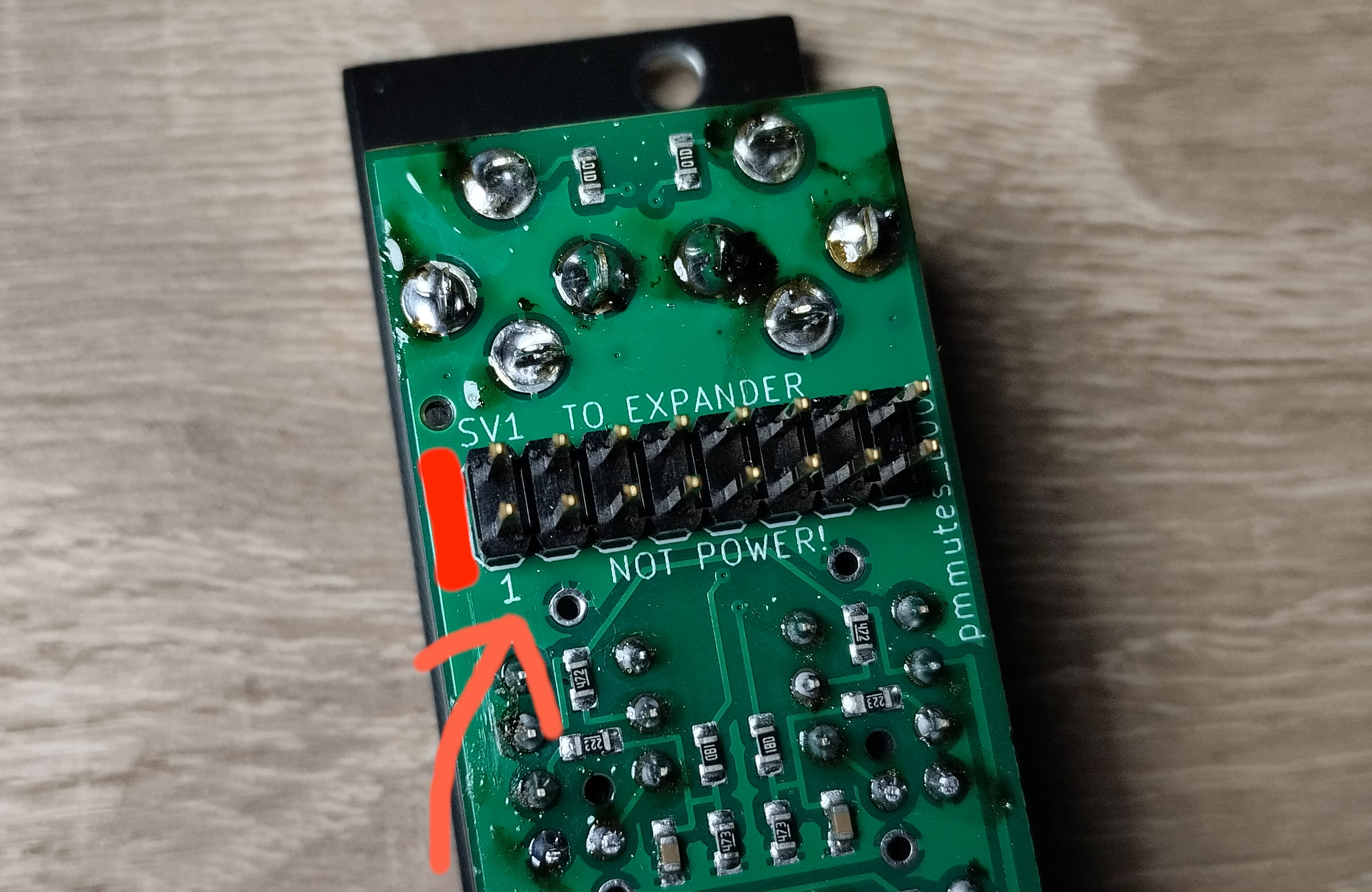
Important note!
Please mind the polarity of your WMD PM connection cable, the stripe should be oriented on the side of pin 1 marking.